
Hit your refresh button to see the latest updates!
The rifling was cut with simple but ingenious homemade machines that pulled a groove cutter through the bore along a spiral path. The spiral path was the result of the cutter being guided by a generally cylindrical guide component that incorporated at least one spiral groove.
One type of guide component is a lathe turned, cylindrical wooden guide roll with external spiral slots. The slots are engaged by fixed-in-place radially oriented tangs, and the cutter is attached to one end of the guide roll. As the guide roll is pulled past the tangs, the spiral slots cause the guide roll to rotate, which causes the rifling cutter to follow a spiral path as it is drawn through the bore of the barrel.
Another type of guide component is a rifled tube with deep spiral grooves. The rifling cutter is attached to a guided component with radially outward projecting features that engage the deep grooves of the rifled tube. As the guided component is drawn through the rifled tube, it turns, causing the rifling cutter to follow a spiral path as it is drawn through the bore of the barrel.
There is no standardized nomenclature for the components of rifling machines. Keep that in mind as you review the examples included below, which originate from more than one source.
This page is part of an online project that features the old-time guns and gunsmiths of Bedford and Somerset counties, Pennsylvania.
L. Dietle


The following photo shows an antique rifling cutter from Somerset County, Pennsylvania. The silver colored feature is a section of lead that has been cast inside the unrifled bore of a barrel. The rifling "saw" is held in a groove that has been cut into the lead feature.


The barrel, now ready for rifling, was taken to the rifling machine, or bench, as we called it, a contrivance simple enough in its working but not easy to describe.
It consisted of a hard wooden bar of cherry, three inches in diameter by four and one-half feet long, with four deep radial grooves, each making one turn in four feet, extending from end to end. To the proximal end of this bar was fastened a loosely revolving handle and to its far end a chuck for holding a steel rifling rod. The wooden bar passed through a ten-inch dialed headpiece whose circumference was divided by deep rectangular notches into eight equal parts, while from its round central opening there passed into each of the four grooves on the bar an iron lug to hold it in place. This arrangement was to set on a frame in smoothly working longitudinal guides.
The barrel was clamped into the frame with its axis in direct line with that of the spiral wooden bar. Into a piece of tough hickory wood, rounded to closely fit the bore of the barrel, a piece of thin, very hard, sharply toothed steel was set to act as a saw or cutter. This section of wood was now connected with a rigid steel rod the length of the barrel and fastened in the chuck.
The cutter, kept well oiled, was pushed back and forth, the guides on the central bar carrying it around spirally, until it no longer bit, when the dial was turned one notch and then another until all of the right rifle grooves had been well started.
The saw was now taken out of its bed and elevated by having a shim of paper placed under it and the work done over and over until the rifles were as deep as desired. With sharp saws and good working iron, a neat job could be done in about two hours. Burrs were smoothed off and the calibre polished with lead plugs and fine emery powder."
The indexing block, and the spiral cut roll can be clearly seen in the photos. In use, the indexing block would be bolted to a rifling bench, in line with a pair of bench-mounted clamps that held the barrel. The rifling cutter was attached to the end of the guide roll, and was moved spirally through the bore of the barrel by the reciprocation of the roll.


After I posted the preceding three photos online, a gun collector wrote the following to me: "That is the rifling machine I purchased and I got it from Collectors Firearms in Texas. At one time it was owned by Dr. Hugh Benet of Maryland but I have not been successful in contacting his family. I found his obituary. He was a collector and historian. I sure wish I knew whose machine it was. All the folks in Texas know is that it came from Pennsylvania."
The following photo shows a guide roll being turned on a homemade wood lathe that is called a pole lathe. The up and down motion of the leather wrapped around the roll turns the guide roll back and forth past the hand-held cutting tool. The downstroke of the leather is provided by the foot treadle. The upstroke is provided by the bent sapling.

The following photo shows an oak strip being wrapped around the guide roll to lay out the locations of the spiral slots.

The following photo shows an individual cutting out the spiral grooves on the guide roll.

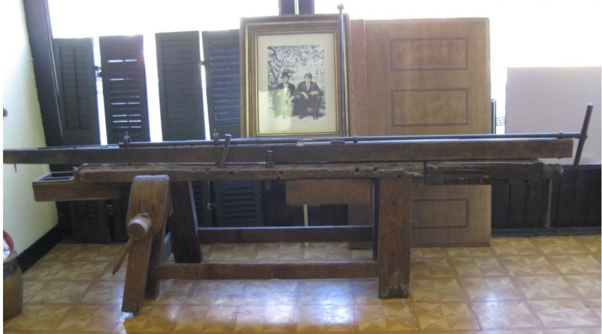
The following photo shows the finished rifling machine being used to cut rifling in a barrel. The indexing block that turns the guide roll is fixed to the bench. The engagement between the indexing block and the guide roll guides the rear of the sliding frame laterally. The sliding frame, which supports the guide roll, is reciprocated to reciprocate and turn the guide roll and the attached rifling cutter. The front of the sliding frame is guided laterally by tabs of some sort that engage the sides of the plank the frame rests on.

The image that follows is another photo showing a barrel being rifled using the homemade rifling machine.


The following image is Plate 62 from the 1924 book "The Kentucky Rifle". In that book, the caption states, "Outside the Henry rifle works at Boulton, Pa. Charles Henry, the last of the great family of riflemakers, is giving a demonstration to the author of the method pursued in rifling a barrel. (Photograph taken November 18, 1921.)" In the photo, the guide component is a rifled tube.

For additional information about how to cut rifling, see Ned H. Roberts' book "The Muzzle-Loading Cap Lock Rifle" (Granite State Press, Manchester, New Hampshire, 1940), which shows photographs of several rifling machines, and includes a description of their use.
![]() Visit the Gunsmith Index for information on various old-time gunsmiths in Bedford and Somerset counties, Pennsylvania.
Visit the Gunsmith Index for information on various old-time gunsmiths in Bedford and Somerset counties, Pennsylvania.
Go to the Lepley gunsmithing page
